Fishing boat engine for Tonga Project

1 Pages 1-10

▲back to top

1.1 Page 1

▲back to top
.� -�Ot,tp.A�JSo� _1A6lE:_ Df Mfdt\\ ���1t-1e foR iotl(:ft\\ PRoJ"Eq'
MA!<ER
YANMAfZ
ltfM
-----· --
·- -
------------ ·-··- -- ..
-- --
Nll(fAfA
HANSHIN
- ---------·---- - ·- -- -
____M_Of)£10F £tl(n: rH:_________ :___ Mf 24.��r__________bM ZZ(ff_________b_Lz4��-- _
A�ASAKA
NH !2�
·__ MlEQ our Pu!_____P� ____·, o o _ ____ __ _ .. ; o_Q __ · __ ,_o_ q_____ _ . s- o o__ _ __
___RA1H) Rf1oLllfloN RPt-1 . _ 4}_Q ___ _ 4_4:J:;..__) _, ·---··-· 4 D_O__,__ f,.�--- _
�-H...Q:i_Qfi_(1Jttt�f� --�___h__ . _______b --------·---·-·-b·--·-----·-- _____ h ___
. ___ C{L:�i)2R BO�� .. ___ t'}l1in1 _ -- . 2.4 0
iio
2.4 D
i i.o...
('(LINfJER Sf~OKt ,mt,;1
42Q
,io
4 0 t)
~ q0
PRf55UR£ MEAH ~/w?
q,4
/1.,1b
I 0, 3 b
I J.'1&
P~HSIJfzf MAX, K2 /w,.1.
qo
l◊0
?O
ao
. .. 1.1.1.c. ;f11N sP' EEf)
'111/4
Ex H,_CrAS 1£t-<f
0(.,
f,Q Cctfsur�Pf:oi-! 8/P$h
_ . { n,t L,cv" ID. WO kroP/1.:i).
;,:;err,:r::,l .
, Sf
cu,.rrR�r•.'
0
H�1
, . M P.ur•W...-!tl�f
L- D l.O~SuMpr10M
r't'OR
8/Psh
?, gg
� I 11.
?. i D
I i:;;q t3b/.
� �?
I t;" B + 3 �/P
Rw t!OI
----1·-D - 80
(<w Nol
'7
o
..
&o
0,8
I. z
~\\ ?3
34 o
I bi:; t 3.'/o
Rw 1101
10-g'D
t,.,r:_-_Q,
:; 1. 0
i bb )' "t/~
~w t-lol
10 - ~o
�.o. i_ . ..
.J.rr.Jl<"Gu.U·
-
.,.-:.1trIiWf 'f-11f..1i t"
fJ
1\\.
vrr?- 100
NAPIA NHP-l�A ,Z:fR-100
AtRtoOLf.f<
WE!CrHJ_OF f�q-iNf____ fol't
/tJSfALlt0
12. 4
!NSfAL�ff)
I 0, q
Norl
I l'\\STA 1.-LH)
q.i
IO, b.
-BATE OF f11!.Sf EHq'INt.
SoppLY Nt.1t-16t�
H6, 1q01
2q
Af7R. lq'1i
J5

1.2 Page 2

▲back to top
51
l
I t""l I -I I I ,i
~ ~ - ~ - - - _·t:, ~"'l:\\r.J.d=/..
'
636 l
I
.0...
CIC)
'""'I
1/...)
10
N
::,t -
X>
1/)
i,-,-.
t
~I
.4
8.1

1.3 Page 3

▲back to top
'e. ·:·: -.:::; ::.:..=f
-·- -:-:--����r+��=--:--+---:-:-:--i-��---;.__.!.+-- ·:·::....,L.I.i:.._.:..;µ;..·_._.::....: :··.:. .c:.::- .....·...·:·::.·.i.·.::.:..·:.·:
-. ·
:•
··-1,-··
::
.
.
..
f•
·,·..�, -
·. ·.:•:·::u,t..
! ·:-·-•---·
:t:, . 'C'."
..7• "
pL
: • • ·I• .: .•.. . '.Di. • .: - ·,
:J -'-·+: -� ,� .. ---•. ·:. I
'.
l • •·
!
... .. :. :.:;:.;.�iII
-+-- . ..-.---.-..-'-".-..... 100-·
..
~f::~ ·:=:::~:-~;j~~~~ ~f[~~~ ;.~;!~:~: ~~~: ! : ~ ~ : t ;~~~i~=~:
-.·rI•·.--. -+-.- . :,.·- ::::..
~_-_=_-.:...:4..:::--~j~·...::··-·-F··::·.:-.·,::...· :-:···-:·.·:::.:..···.:-=.:-=:.-.:.-+:- .:-:-..-:-·-: .:- ·:};.--.-::-::.-;: . .. �.:.-=:J:�+�-:.i:..:-�-
·•···T:.::: .. ·
!' ··:·-:·..
····:-�1
:.·:
····.- .·· .
1
-90·· 200-
8-8
I ,.· · :.f.¼ffi.:_,
��r.�-F����-i:-����+.-�d.:.,..;..:..;.:.4,.:...:.:.:---l�-
. :.:- -:,:;-�- L·
-:__ _:._ -�
__ ;_s_�
__
_:__; . _;.i:...________
-. .-.. J-: : .. . ; .
_
.
·7t)-
..
.·.
.
!. :
..:.···!.-
.
..:::
...
..:
- ..
.:: ..;.:. ~·.
":-:t:~4~:::::~~~~~7""'.:--:-:-=-+-:~-:-:-=--E.~:--F~~~.;..,..;............_;.,;._+;,....;.·_· ·..;.,t.:·: . . ~ - - _........,_ _
, . : ..
. : . r-: - y -··--·····
. ·! ..: :-· -�. : :: .
I
..·. - ..!' .. . -

1.4 Page 4

▲back to top
Spec. No. F24-002
STANDARD SPECIFICATIONS
600 � 950PS Marine Main Diesel Engines
MF24 SERIES

1.5 Page 5

▲back to top
-1-
1. General
1-1. Application
This Specifications shall set forth standard specifica­
tions of Yanmar MF24 Series marine main engines.
1-2. Applicable standards, appointed date of delivery,
color of painting, etc.
Applicable standards, guarantee, appointed date of
delivery, place of delivery, method of delivery, type
of packing,color of painting, etc. shall be as per
separate papers.
1-3. Miscellaneous
1) In addition to these specifications, optional
parts and devices for such as special specification
of the engine, remote control equipment and auto­
matic controller required by applicable standards
are available from Yanmar.
For these particulars, please refer to the separate
Consultation Specifications.
2) The contents of this Specifications may be altered
without an advance notice for improvement over
engine performance and other reasons.

1.6 Page 6

▲back to top
-2 -
2. Major Specifications of Engine
·1 Type
Vertical, single-acting, 4-cycle, direct injection,
supercharged (turbo-charged), water-cooled diesel
engine
2 !Model
MF24-HT
MF24-DT
MF24-0T
MF24-ST
IRated output (ps)
3
I (No. of horsepowers
!based
I
on
Fishing
Boat
!Law}
4
!Rated
(rom)
revolutions
I
I
., I .i.:. 111.0. of cx .....;.n...e;s
I
l� tiolninder configura­
7 !Cylinder l:x>re (mm)
600
(400)
700
(400)
800
(400)
420
6
Series
240
950
(400)
B !stroke (mm}
I
420
I I Total stroke volume
9 (1)
114.4
IBrake mean effective
10 pressure (kq /cm 2 )
ll.28
13.16
15.04
11
Mean piston speed
(m/sec.)
'
S.88
l. 2
Combustion max.
.output (kg/cm2 )
<100
<100
<110
. I l3 ., Direction -of rotation Clockwise as viewed from the flywheel side
I
..
114 IEngine (c!...--y) weight
12,400
12,400
13,000
17.86
<110
13,000
I
15
Configuration
of crank
16 !Firing order
.I17 Fuel used
I
18
Lubricating oil
used
G
A
As viewed from flywheel side
2.s
3,4·
- j1 - 4 2 - 6 - 3 - 5
!HtheaevyengoiilneAin(olfet}leosrs
than Rw. #1
heavy oil B
65-sec
viscosity at
Engine system oil, API Service Grade CD oil; super-
charger (turbo-charger) oil, �ineral turbine oil;
valve rocker arm oil, exclusive low-viscosity oil;
governor oil, engine system oil or mineral turbine
oil; hydraulic remote control oil, mineral high-
quality hydraulic operating fluid.

1.7 Page 7

▲back to top
-3-
,---
A) Machine side start/stop (manual start, manual and
Starting/stopping
19 system
-
20 ,� eou1.Ptmeenctontrol
remote emergency stop)
B) Machine side start/stop and trouble stop (manual
start, manual and automatic stop with remote
emergency stop)
lCompressed air start (max. starting air pressure:
30 kg/cm2 }
Oil hydrostatic type, 2-handle
IAB) Pnetmatic type, 1-handle (ootional soec.)
Lubricating sump
II2t 1
system
Lubricating system
It
!I
I
;22 Cooling system
I
I
1:723
I
S�percharg�g
sv. stem
24 Turning system
A) Engine bed plate internal sump - wet sump system
B) Hul.l equipped sump -- dry sump syste.I.l (optional
spec.)
Forced lubricating svstem bv engine eauioped oumo
- Cylinder, cylinder head a..�d turbo-charger by sea
11 water
- Lu.b. oil cooler and air cooler by sea water
- Piston by lub. oil
L* Cylinder, cy�.L-ider t..aad and turbo-charger may also
[
L be cooled by fresh water according to the separate
r Soecifications.
IBwiythexahiarustcooglaserturbine supercharger (tur!x>-charger)
11Turning bar
II
25 Overload
j10, overload for 60 min.
26
Specific fuel con­
sumption (g/PS•hr.)
157 + 3%
I
155 + 3\\
I(under 100% load, heavy oil A, low calorific power of
10,200 kcal/kg)
l21 Specific lubricating
oil consumption
L (g/PS•hr.}
,
Less than o.a
(under 100\\ load)
I
28 Speed regul.ation
'
I.nstani:aneous, within 13%; setting, within 7\\
Change of load: 0.3 by 100\\
- Sea water temp.: Bel� 32 °C
29 Conditions of use
I- Sea water engine outlet tel:lp.: 40 '\\. 45 °C
- Ambient temp.: o � 45 ° C
- Exhaust · back pressure:
Less than 350 mm Aq.
(under 100% load)
Engine interior (piping interior): 5 i
.
I.uh. oil cooler: 301
30
Lubricating oil
holding volume
Turbo-charger: 0.8 i
Lub. oil sump (engine bed plate interior): 300 i
Valve rocker arm oil tank: 2 i
Reversing gear:
60 i for MF24-HT, OT
BO i for MF24-UT, ST

1.8 Page 8

▲back to top
4
3. Major Specifications of Reversing Gear
l Type
2 'Model
--
Input/output shaft
3
revolutions (under
the rated output)
Crom)
4
Direction of
rotation
5 !Reversing system
l Input and output shaft coaxial., hydraulic reversing
!gear with clutch
! Model MN6ll for MF24-HT, OT
Model MN70l for MF24-UT, ST
420
-
- Input sha.£t:. Clockwise as viewed from the stern
- output shaft: In ahead, clockwise as viewed from the
stern.
In astern, counterclockwise as viewed
from the stern
i
!constant mesh gear
I
6 jciutch
!wet, multiple disc,· hydraulic operating
- Reversing gear oil (incl. clutch hydraulic fluid):
- 7 Lubricating oil used
API Service Grade.CD oil (same as engine system oil)
Clutch remote operating oil: Mineral high-quality
hydraulic fluid (in the case where a hydraulic
remote control equioment is eauipped)
a.
Reversing gear (dry)
weight {kg)
Model MN6ll:
Model MN701:
1,600
21 200
Lubricating oi.l sump Reversing gear body lower case interior sump --
9 system
Lubricating system
10 !cooling system
wet system
Forced lubricating system by machine.equipped
1-hydraulic oil pumn
Lub. oi.i.. cooler by sea wat:er
•.
- Gears and clutch bv lub. oil
4. Major Specifications of Applicable Shafting Equipment
[ Item
' Properller· rated re-
I MF24-HT
I
volutions {r;:xn)
Intermediate shaft
diameter {mm)
140
Propel.ler
shaft dia-
meter (mm)
1st
category
I 2nd
cateqo�
.150
160
I Propeller diameter (mm) l,53Q"\\,l,600
MF24-DT
MF24-UT
MF24-ST
420
l.50
I
160
160
I
I
170
160
I 170
I l,570"-l, 650 ·1 l,62Q"\\,l,700 l,66Q"\\,l,750

1.9 Page 9

▲back to top
- 5-
Notes: 1) Propeller diameter mentioned above is for the
case of a 4-blade propeller and has been
calculated on the basis of about 10 knots
for ship's speed.
2) The first category of propeller shaft
refers to the case of a solid sleeve or
rubber wound shaft; the second category,
the case other than first category.

1.10 Page 10

▲back to top
-6 -
5. Material and Construction of Principal Parts
Description
1) Bed plate
Material
Cast iron
Construction
Solid casting
2) Cylinder block -Cast iron
Solid casting
Forming the crankcase with
the bed plate and constructed
to possess the water jacket
part in between it and the
cylinder liner.
3) Cylinder liner
Special
cast iron
Wet type
4) Cylinder head
Cast iron
MF24-HT, DT, UT: 2-valve
type ( O!le suctio!l ".T::!.lve a!"ld
one exhaust valve)
MF24-ST: 3-valve type· (two
s·uction valves · and one
exhaust valve)
5) Piston
Cast iron
Solid casting
Cooling: Shaker cooling of
the inner surface with lubri­
cating oil
6) Piston pin
Special
steel
Floating type
7) Connecting rod
Forged steel
Assembled construciton of
fitting the phosphor bronze
piston metal to the small end
part and the large end part
split with the crank-pin
bearing.
8) Crank-pin metal
Alloy layers
Thin 4-layer finished metal
of such that its back metal
is steel, . intermediate layers
of kelmet and white metal,
and surface layer by thin
soft alloy plating.

2 Pages 11-20

▲back to top

2.1 Page 11

▲back to top
-7-
Descriotion
9) Main bearing
metal
10) Crankshaft
11) Cam shaft
12} Reversing gear
body
13) Output shaft
14) Clutch
15) Bearing
Material
Alloy layers
Construction
Thin 3-layer finished metal
of such that its back metal
is steel, intermediate layer
of white metal, and surface
layer by thin soft alloy
plating.
Forged steel Forged type, polishing
finished
Carbon steel Cam is of the separate
piece incorporating type;
shaft, one-piece type.
Cast iron
Horizontally split-into-
two type, clutch and thrust
shaft bearings built-in type
Forged steel Input· -· :output shaft coaxial
type
Sintered
Wet, multiple disc, hydraulic
copper alloy type
Ahead side provided with
emergency setbolt.
Special steel Thrust bearing: plane
metal

2.2 Page 12

▲back to top
- .8 -
6. Equipment
6-1. Engine body related
Description
1) Indicator cock
Q'ty/
unit
6
Soecification
Remarks
6-2. Cooling water system
1) Cooling water
pump
1 Type: Centrifugal For engine
Capacity: 15m 3 /hr. cooling
Total'head: 15m
water
2) Cooling water
pump
1 Type: 1.SkW,
For cooler
motor-
cooling
driven,
water
centrifugal
(equipped
Capacity: 15m 3 /hr. to th.e
Tota.l head: 15m
hull)
Power source:
AC 220V,
60 Hz
3) Cooling sea
water thermo-
static valve
l Type: Manual globe For engine
valve
cooling
Using std.:
water
Engine outlet
cooling water
temp. of.
40 "' 4s 0 c -
4) Cooling water
6
flow rate re-
gulating valve
for each
cylinder
5) Emergency cool- 1 set SOA, w/spectacle
ing water inlet
blank flange
For engine
cooling
water
6) Emergency cool- 1 set SCA, w/spectacle--
ing water inlet
blank flange
For cooler
cooling
water

2.3 Page 13

▲back to top
- 9 ·- -
Description
7) Kingston valve
Q'ty/
unit
2
Specification
Nominal dia.: SK-50
Remarks
(Equipped to
the hull)
8) Cooling sea
water strainer
2 Type: Duplex.
(Equipped to
change-over the hull)
9) Anticorrosive
, material
1 set Cylinder: Al
Others: Zn
10) Cooling water l set Major parts: Steel
engine internal
pipe, galvanized
piping
11) Air cooler cooling
water flow rate
regulatinq valve
Notes: Customer's procurement
For boost:
air temp.
control
1) Bilge pump (40A - 10m 3 /hr. x 10m x 0.7SkW)
2) Emergency cooling water pump (SOA - 15m 3/hr.
x 15m x l.SkW)
3) Inboard fitting-u_ p piping materials for
cooling water system (2.SA, 40A, SOA, etc.)
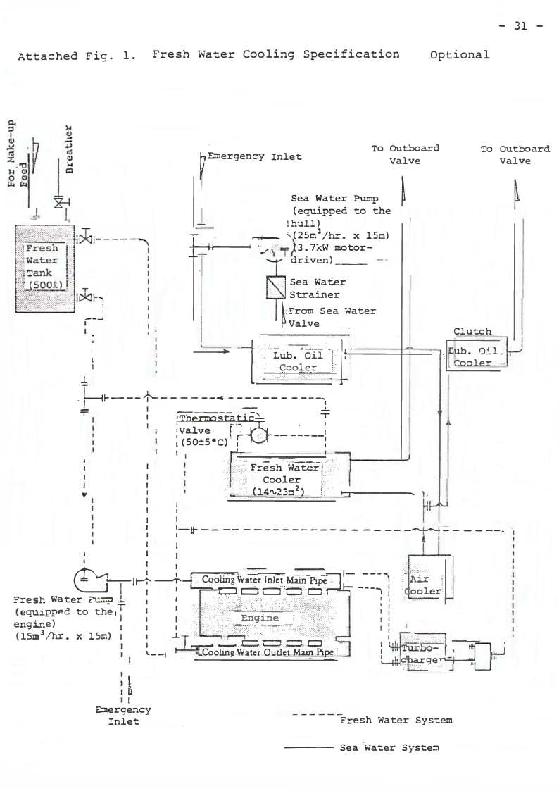
4) Fresh water cooler (cooling area of 14 � 23m2 ,
..
w/fresh water automatic thermostatic valve) .••
in the case of cooling the engine with fresh
water ••• optional spec. -- Refer to
Attached Fig. 1.

2.4 Page 14

▲back to top
- 10 -
6-3. Fuel system
Description
1) Fuel injection
pump
Q'ty/
unit
6
Soecification
Bosch, each cylinder
independent type
Remarks
2) Fuel settling
tank
1 Type: Oil-water
separating
plate
built..:fi1
Capacity: 30.t
(Equipped to
the hull)
3) Fuel oil
1
strainer
(No. 1 strainer)
Type: Auto-clean,
150 mesh
(Equipped to
the hull)
4) Fuel oil
1
strainer
_(No_. 2 strainer)
..
5) Fuel injection
6
valve
Type:
Duplex,
change-over,
notch-wire,
200 mesh
Multijet, uncooled
type
(Equipped to
the hull)
6) Fuel engine
1 set Major parts:
internal piping
Steel pipe
Notes: Customer's procurement
1) Inboard fitting-up piping materials for
fuel oil system (15A, 32A, etc.)
2) The fuel feed pump may be equipped
optionally.
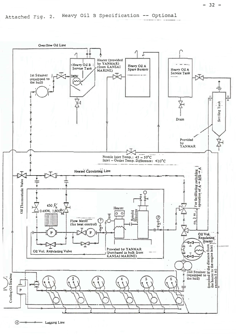
3) Heavy oil B using equipment may be equipped
optionally. Refer to Attached Fig. 2.

2.5 Page 15

▲back to top
- ll -
6-4. Lubricating oil system
·Q'ty/
Descriotion unit
Soecification
1) Lubricat�ng oil 1 Type: Gear
pump
Capacity: 18m 3/hr.
Safety valve set
pressure: 8.0kg/cm 2
Remarks
2) Lub. oil pres­
l Set pressure:
sure regulating
2.0 "' 3.0kg/cm 2
valve
3) Lub. oil
strainer
1 Type: Duplex,
For pump
change-over, outlet
notch-wire,
150 mesh
4) Lub. oil
cooler
1 Type: Multitubular (Equipped to
Cool'ing area:
7.28m 2
the l}ull)
5) Valve rocker
arm lub. oil
sump
1 Capacity: 2.t for .MF24-HT, DT, UT;:
15.e. for MF24-ST.
6) Lub. oil
thermostatic
valve
1 set Manual type
{Equipped to
the lub. oil
cooler)
7) Emergency lub. l set 40A, w/spectacle
oil inlet
blank flange
8) Lub. oil by-
1 set Inlet: 25A
pass strainer
O.utlet: 25A
inlet and outlet
9) Lub. oil engine 1 set Major parts:
internal piping
Steel pipe
Notes: Customer's procurement
1) Emergency lub. oil pump (40A - 16m 3/hr.
x 3.Skg/cm 2 x S.SkW)
2) Inboard fitting-up piping materials for
lub. oil system (25A, 40A, etc.)

2.6 Page 16

▲back to top
- 12 -
6-5. Suction and exhaust systems
DescriEtion
1) Air cooler
Q'ty/
unit
1
Soecification
Type: Circular finned
multi tubular
Cooling area: 2lm 2
2) Suction valve
6 For MF24-HT, DT, UT
12 For MF24-ST
3) Exhaust valve
6 Valve box type
4) Exhaust gas
1 Model VTR200
turbine super-
charger (turbo-
charger)
5) Exhaust ex-
pansion joint
1 For turbo-charger outlet
6) Suction manifold 1 set
7) Exhaust mani-
fold
1 set
Note: Customer's procurement
..
1) Inboard fitting-up piping materials for
exhaust system (200A, etc.)
6-6. Governor gear
Description
1) Governor
Q'ty/
unit
SEecification
1 Model RHD6 hy draulic governor
2) Hydraulic piston l
of the passive
part
For governor

2.7 Page 17

▲back to top
- 13 -
6-7. Starting air system
Description
Q'ty/
unit
Soecification
1) Starting valve
6
2) Starting air
1
stop valve
3} Starting air
1
distributing
valve
4) Starting air
1
control valve
5) Starting air
main pipe
1 Stee.l pipe,
galvanized
6) Air reservoir (1/
Capacity: 80.2. X 2
vessel.)
Remarks
(Equipped to.
the hull}
Note: Customer's procurement
l} Inboard fitting-up piping materials for starting
air system (20A, etc.)
6-8. Installing and direct coupling parts
Descriotion
1) Flywheel
Q'ty/
unit
l
Soecification
2) Flexible coupl- l set Rubber block type
ing
3} Foat liner
1 set Thickness: 45.mm
One-side finishing
4) Installation
bolt and nut
5) Jack bolt
(upper and
lower jacks)
, set M27, doubble nut
type
1 set M24 X 145mm
Remarks
For both
engine and
reversing
gear
For engine
For engine
and reve.::-s­
ing gear
alike

2.8 Page 18

▲back to top
- 14 -
Notes: Shipyard's procurement
1) Installation position adjust fittings
2) Reversing gear mount (as there is a step
(difference in level} between the engine
installing surface and the reversing gear
installing surface)
6-9. Gauges and meters
Description
Q'ty/
unit
Soecification
Remarks
1) Pressure gauge,
Model DVU60
Lub. oil
l
Provided on
the gauge
panel.
Cooling water 2
For engine
and cooler
Boost air
Fuel oil
2) Tachometer
1
l Oil A (optional spec.),
,
oil B (standard spec.)
100¢ mechanical
Provided on
type
t.pe gauge
panel.
3) Gauge panel
1 Vibration-proof
type
4) Thermometer,
Lub. oil
Cooler inlet l
- Cooler out-
let
l
Cooling water
Engine inlet l
Engine out-
let
6
Air· cooler
inlet
1
Air cooler
---o- u-tlet
·-1

2.9 Page 19

▲back to top
- 15 -
Descriotion
Exhaust
- Each
cylinder
outlet
T urbo-
charger
inlet·
Boost air
- Air cooler
outlet
Q'ty/
unit
6
2
l
Specification
Remarks
6-10. Reversing gear body related
Description
1) Hydraulic oil
pump
Q'ty/
unit
1
Specification
Type: Gear
Capacity: 4.8m 3 /hr.
for Model MN611,
6.3m 3 /hr. for Model
.MN701
Safety valve set
pressure: 20kg/cm 2
In-common type with
lub. oil p�p
2) Lub. oil
strainer
l Suction side
Type: No�ch-wire,
60 mesh for Model
MN6ll, 32 mesh for
Model MN701
Discharge side
Type: Auto-clean,
150 mesh
3) Lub. oil
cooler
1 Type: Multitubular
Cooling area: l.lm 2
for Model MN611,
2m 2 for Model MN701
Remarks

2.10 Page 20

▲back to top
- 16 -
Description
4) Hydraulic oil
pressure re­
gulating valve
Q'ty/
unit
1
Soecification
Set pressure:
14 "" 15kg/cm 2
Remarks
5) Lub. oil pres­
1 Set pressure:
sure regulating
3.0 "" 4.Skg/cm 2
valve
6) Clutch ahead -
1 w/rotary control
astern (hydrau­
lever
lic oil)
change-over
valve
7) Clutch ahead -
astern change­
over detector
1 Pressure detecting Contact
relay, w/20a
capacity:
gland
DC 24V, 3A
8} Pressure gauge,
Model DVU60
Hydraulic oil 1
Lub. oil
1
Provided on
the engine
gauge panel.
9) Thermometer,
Lub. oil
- Cooler out-
let
1
Cooler inlet l
Notes: Customer's procurement
l) Emergency lub. oil pump (Model MN6ll,
4.8m 3 /hr. X 14kg/cm 2 X 5.SkW) (Model
MN70l, 6.0m 3 /hr. X 14kg/cm 2 X 5.SkW)
2) Inboard fitting-up piping materials for
lub. oil system (inlet 25A, outlet 40A -
Model MN611) (inlet 20A, outlet 20A -
Model MN701)

3 Pages 21-30

▲back to top

3.1 Page 21

▲back to top
- 17 -
6-11. Remote control equipment
Note: The remote control equipment has been in
conformity with the Notification·"ship's
Survey No. 177" of the Ships Bureau, Ministry
of Transport.
Descriotion
1) Hheel house
control board
Q'ty/
unit
1 set/
vessel
Soecification
Type: Self-support­
ing (stand)
Control system:
Hydrostatic oil
type, 2-l;landle
Powe·r source:
DC 24V
Board surfaces:
Top and all other
surfaces (front
surface provided
with hinges on the
right and .handle
on the left)
Splicing sleeve and
wire lead-in port:
Lower open type
Splicing sleeve:
6 & 8¢ copper
tube
Power cable:
250V, dry-core
l.25mm 2
Protection circuit
contact: ON in
abnormality
Remarks
2) Hydraulic
piston of the
starting part
for governor
l w/rotary handle,
Incorporated.
governor handle and into the
scale plate
control
board on its
front sur­
face

3.2 Page 22

▲back to top
- 18 -
Description
3) Hydraulic
piston of the
starting part•
for clutch
ahead - astern
changing over
4) Engine rota­
tional speed
indicator
Q'ty/
nnit
Soecification
1 w/lever handle and
-phase control valve
l Type: Electric,
llOrran. 2 wide-angle,
w/internal il­
luminating lamp
5) Control position
pilot lamp,
-Engine room
1
-Wheel house
1
6) Clutch ahead -
astern opera­
tion pilot lamp,
Red lamp
Green la.mp
-Ahead
-Neutral
-Astern
7) Alarm (pilot)
lamp,
l Green lamp
1 Daylight lamp
1 Red lamp
-Engine lub.
oil pressure
drop
-Reversing
gear lub. oil
pressure drop
1 Red la.mp
l Red lamp
Remarks
Incorporated
into the
control
board on its
front sur­
face
Incorporated
into the
control
board on its
front sur­
fc.ce
Incorporated
into the
control
board on its
front sur­
face
Incorporated
into the
control
board on its
front sur­
face.
Incorporated
into the
control
board on ·its
front sur­
face

3.3 Page 23

▲back to top
19 -
Description
-Engine cooling
water temp.
rise
-Cool.er cooling
water pressure
drop
-Remote emer­
gency stop
-No. l aux.
engine ab­
normality
Q'ty/
u nit
1
1
l
l
Soecification
Red lamp
Red lamp
Red lamp
Red lamp
-No. 2 aux.
engine ab­
normality
l Red lamp
8) Automatic stop
pilot J.amp,
-Engine lub. oil 1
pressure drop
-Reversing gear 1
J.ub. oil. drop
9) Push button,
Red lamp
Red lamp
-Lamp/buzzer
test
1 Green
-Buzzer stop
l Red
-Remote
1 Red, w/protective
emergency stop
cover
10) Wheel house
alarm buzzer
1 Incorporated
Remarks
Lub. oil
pressure
drop/cooling
water temp.
rise
(optional)
Lub. oil
pressure
drop/cooling
water temp.
rise
.�
(optional)
(Optional)
Incorporated
into the
control
board on its
front sur­
face
Incorporated
into the
control
board on its
front sur­
face

3.4 Page 24

▲back to top
- 20 -
Descriotion
11} Illumination
regulator
(dimmer) ,
Q'ty/
unit
Soecification
-Pilot lamp
-Rotational
speed indi­
cator
12) Engine room
alarm panel
13) Control
position
pilot lamp,
1
1
l ass J y/ Type: Wall-hanging
vessel Power source:
DC 24V, l "- 2A
(normal), 15A
(instantaneous}
Panel surface:
Front surface pro­
vided with hinges
on the left and
handle or. the right
Wire lead-in port:
Lower coming type
Switch.: Power
(l pc.), alarm cir­
cuit power (1 pc.),
(optional) aux.
engine alarm cir­
cuit power (2 pcs.)
Protection circuit
contact: ON in
abnormality
-Engine room
-Wheel house
l. Red lamp
1 Green lamp
Remarks
Incorporate
into the
control
board on it
front sur­
face
Incorporate1
into the
alarm panel
on its fron·
surface

3.5 Page 25

▲back to top
- 21 -
Descriotion
Q'ty/
unit
14) Clutch ahead -
astern opera­
tion pilot lamp,
Specification
-Ahead
-Neutral
-Astern
15) Alarm (pilot)
lamp,
1 Green lamp
1 Daylight lamp
1 Red lamp
-Engine lub. oil 1
pressure drop
-Reversing gear 1
lub. oil pres-
sure drop
-Engine cooling l
water·temp. rise
-Cooler cooling 1
water pressure
drop
-Remote emer­
1
gency stop
,
-Aux. engine
2
lub. oil pres­
sure drop
-Aux. engine
2
cooling water
temp. rise
16} Automatic stop
pilot lamp,
Red lamp
Red lamp
Red lamp
Red lamp
Red lamp
Red lamp
Red lamp
Remarks
Incorporated
into the
alarm panel
on its front
surface
Incorporated
into the
alarm panel
on its front
su.rface
(Optional)
(Optional)
Incorporated
into the
alarm panel
on its front
surface

3.6 Page 26

▲back to top
- 22 -
Description
-Engine lub.
oil pressure
drop
-Reversing gear
lub. oil pres­
sure drop
Q'ty/
unit
1
1
Soecification
Red lamp
Red lamp
17) Push button,
-Lamo/bell test 1 Green
-Bell stop
1 Red
18) Engine room
alarm bell
1/
Type: 120¢
vessel separate installing
type, w/pilot lamp
Power source:
DC 24V, w/20a gland
19) Engine rota­
tional speed
transmitter
(tachometer
generator)
1 .Type: Electric,
w/lSc gland
Voltage generated:
AC 25V/420 rpm
Remarks
Incorporated
into the
alarm panel
on its front
su rface
(Equipped to
the hull)
(Equipped to
the engine)
Notes: Customer's procurement
1) Inboard fitting-up piping materials for
remote control oil system (6 & 8mm¢
copper tube)
2) Inboard fitting-up wiring mater ials
(250V - dry-core - l.25rnm2 , 250V - DPYC -
10, 250V - TPYC - 4)
(250V - dry-core - 2.00mrn2 , 250V - DPYC -
1)
(250V - MPYC-27 - 1)
·J

3.7 Page 27

▲back to top
- 23 -
6-12. Protective device
Description
1) For alarm,
Q'ty/
unit
Soecification
-Engine lub.
oil pressure
switch
1
ON at l.6kg/cm 2
OFF at l.9kg/cm 2
-Reversing gear 1 ON at 2.9kg/cm2
lub. oil pres-
sure switch
OFF at 3.2kg/cm2
-Engine cooling
1
ON at ss 0c
water temp.
switch
-Cooler cooling 1 ON at 0.lkg/cm2
water.pressure
switch
OFF at o_.2 kg/cm 2
2) Engine stop
device
1 Type: Electric
solenoid, DC 24V,
9A
When energized, it
stops the engine.
Remarks
Contact: ON
in abnormali t)
Contact
capacity:
DC 24V, 3A
w/20a gland

3.8 Page 28

▲back to top
- 24 -
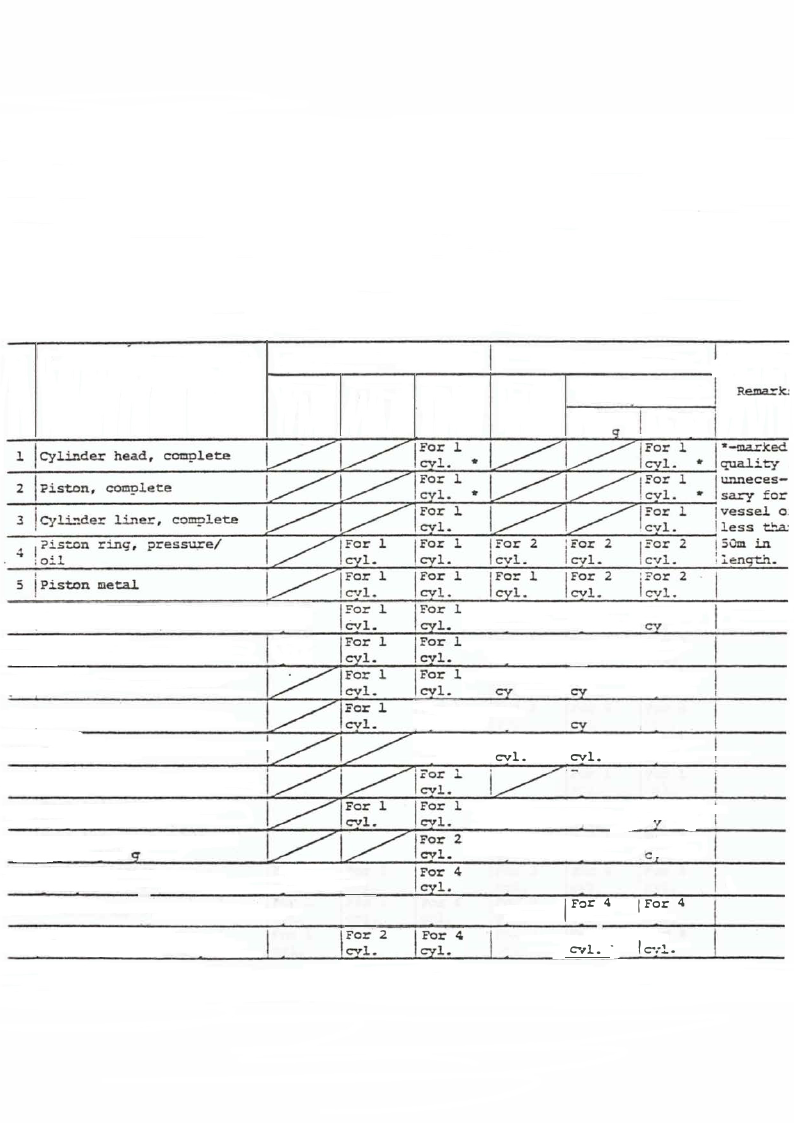
6-13. Spare parts lis t, standard
The following spare parts shall be p�ovided per vessel
on the basis of navigation area and rules.
Ship's navigation area
Fishing Boat Rul.es
No.
Description
Smooth Coast­ Greater 1st
2nd & 3rd
catecories
Rema=k.:
water ing coasting category <501!1
>50m
lon
lonq
l !Cylinder head, coaplete
2 !Piston, complete
I3 C-.1li."1der liTler, complete
4
l ?ist.on
;oil
ring,
pressu;re/
*
For l
cvl. *
!For l.
cvl.
IFor 2
cvl.
!For 2
cvl.
jFor l , •-marked
icvL * quality
. 1For l
lcvl.
l unneces-
sary for
!='or l
cvl.
1=0: 2
C V .!..
jvessel o.
!less tba:
1s0m in
: i.ength..
I
5 !Piston metal
6 Ilcrank--cin metal.
7 jcrank-pin .bolt & nut
I For .l
cvl.
For l.
cvl.
For l
1.
For l
cvl.
IFor 1
cvl.
For 1
I cvl.
IFor 2
cvl.
I For 2
cvl.
For 2
'cyl.
:For 2
l cv1.
IFor 2
1.
'cFoyrl. 2
a !suction valve, cocplete
IFor 2
1.
'For1. 3
!,Fcovrl. 3
9 l==xhaust valve, complete
IFcovrl. 1
For
'cvl.
3
IForl. 6
!Fcovrl. 6
lO !starting valve, complete
11 !safety valve,-complete
IFor l
cvl.
For l
'cvl.
IFcovrl. 1
I c.::ovrl. .i.
!For 1
I cvl.
·
,
:O�
cvl.
j_
U
;·E'Uel injection
l conrolete
valve,
I .For 2
cvl.
!Fcovrl. 3
!,Fcorl. 3
13 ,� tinel&insjcr� in n va.lve,
14 IEo'lUuenlaeirnjaesc-s-.i-.'yon pump •
!For 1
cvl.
15
!Fuel
injec+-..icn pu:n.p
spring
Fo= l
I CYl.
15
\\Fdeuelliveinrjvecvtaliovne
pump
ass'v
For l
cvl.
For 2
' cyl.
· For 2
I1 cyl.
For 2
cvl.
rt
! For 4
cvl.
IFor 4
cyl.
'Fcovrl. 3
!.Fcovrl. 2
l·Fcovrl. 2
:For 2
cvl.
IFor 3
cvl.
I For 4
cvl.
I For 4
cvl.
1
4
1For
�...1. .
!FCor1. 3
jFor 4
, cvl.
I For 4
1 cvl.
j:'or 4
I �..-1.

3.9 Page 29

▲back to top
- 25 -
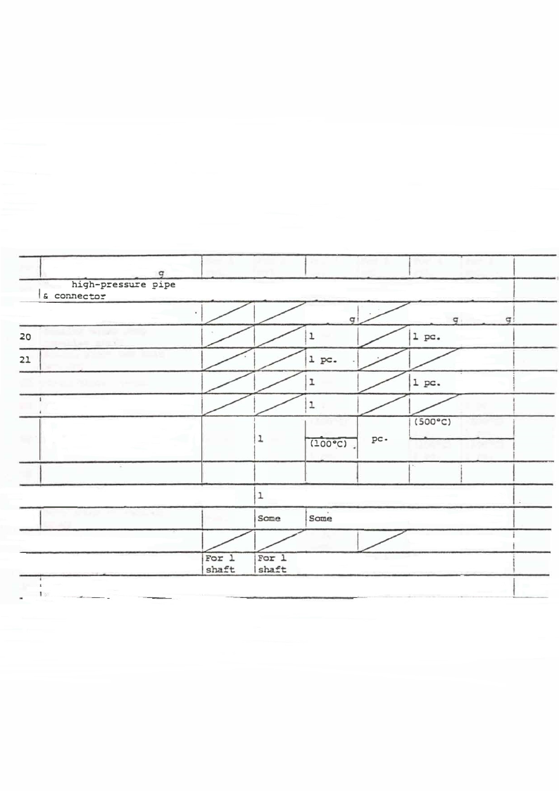
Fuel injection pump
17 deliverv valve sorin g
I18
!Fuel high-pressure pipe
I& connector
Prooeller shafting
19 couolina, bolt & nut
20 'Ciomoolelilnegrwashtaefrtpump
21
Bridge gauge for main
bearina
'Chain 22
block� 2-ton
23 !Indicator
24 Thermometer (l00°C)
25
26 !Denigsaisnseemrobolimngi..m-;t:,loeomlesntand
27
Bolt & nut of various
ki."lds
2S j Special pack.inc;
29
jMain bearing fittings,
lturbo-charQer
30
Main sha!:t gasket
oackin, turbo-charaer
For l
I cvl..
For l
cvl.
1 pc.
'For 2
cvl.
I For l
cvl.
pc.
:or 4 'For 2
I cvl.
cvl.
For 3 I For l
cvl. lcvl.
jFOr 1
lc:,uolin
pc.
.For 4
cvl.
'Fcvolr. 4
-,For 3
cvl.
!For 3
,cvl.
iFor 1 :?or 1
lcou::>lin ;couolin
I 1 pc.
!1 pc.
pc.
12 pcs.
pc.
' 5( 00°C)
t-l,-(1.,0oc0._ ._"C_ )_ ......, l pc.
l PC.
I 1 oc.
(l00°C)
1 pc.
j 1 pc.
I ( 500°C)
i l oc.·
I (l00°C)
1 oc.
Ii set
ISome
IFor l
shaft
!FsoharftJ.
set
Isome
IFor l.
!I shaft
For l.
shaft
Ii set
Isome
12 pcs.
- each
I.For 1
!I shaft
For l
shaft
j1 set
Isome
!For 1
!I shaft
For 1
shaft
I. j1 set Ii set
jsome !some
12 pcs.
leach
jFor .1
lsha:tt
I.For 1
I shaft
j2 pcs.
1eac�
!For l
isna.f�
l,·Fshoarftl

3.10 Page 30

▲back to top
- 26 -
6-14. Tools
The following tools shall be provided per vessel:
6-14-1. Disassembling/reassembling tools
Descriotion
l} Cylinder head lifting
tool
2) Suction/exhaust valve
spring attaching/
detaching tool
3} Supporting base for do.
4) Exhaust valve box
drawing-out bolt
5} Fuel injection valve
drawing-out tool
6} Starting valve draw-
ing-out bolt
7} Piston inserting tool
8) Piston lifting tool
9) Piston fixing tool
10} Exhaust valve box
tightening box spanner
11) Main bearing lower
metal inserting tool
12) Main bearing cap
drawing-out tool
13) Crankshaft forward
coupling circular nut
spanner
Q'tv
1 set
1 set
1 set
1 set
l
2
1
1
1 set
1 set
1 set
l
1
Remarks

4 Pages 31-40

▲back to top

4.1 Page 31

▲back to top
- 27 -
Descriotion
14) Propeller shaft forward
coupling circular nut
spanner
15) Propeller nut spanner
16) Propeller drawing-out
tool
17) Stern tube nut spanner
18) Fuel injection pipe
tightening box spanner
19) Cylinder head clamping
box spanner
20) Fuel injection valve/
starting valve tighten­
ing box spanner
21) Open end,double head
spanner
22) Double-ended spanner
Q'ty
1
1
1 set
l
1 set
1 set
1 set
1 set
1 set
23) Blade screwdriver
l
24) Monkey wrench
1
25) Main bearing incorporat-
1
ing/assembling wrench
26) Hammer , rnidium-sized
1
27) Single-hand hammer
1
28) Pincers
1
Remarks

4.2 Page 32

▲back to top
- 28 -
6-14-2. Servicing tools
Description
1) Suction/exhaust valve
grinding tool
2) Exhaust valve grinding
base
3) Starting valve grinding
tool
4) Fuel pump priming handle
5) Flywheel turning handle
6) Fuel pump tappet
adjusting spanner
Q'ty
l
l set
l set
1 set
2
l
Remarks
... ---
7): Clearance gauge
8) Oil grind stone
9) Oil feeder (oiler)
10) File
11) Packing
1 set
1
·1
l
l
Bas·tard cut, ..
half-round
300
12) Nozzle tester
13) Nozzle teste::- connect-­
ing pipe
1 set
l

4.3 Page 33

▲back to top
- 29 -
7. Test, Inspection, Etc.
7-1. Indication
1) Scale units of name plates
and gauges and meters:
Metric system used
2) Language used for name
plates and caution plates:
English or Japanese
7-2. Shop test/inspection
1) Starting test
2) Load running test
a) Ahead run
i} With 25% load* for 20 min.
ii) . With 50% load* for 20 min.
iii) With 75% load*.for 20 min.
iv) With 100% load for two hrs.
v) With 110% load for 30 min.
vi) With 3.7% minimum-speed load* for 2d min.
b) Astern run
i) With 75% load* for 20 min.
3) Bearing temperature measurement
4) Reversing gear temperature measurement
5) Remote control equipment performance test
6) Overhaul inspection

4.4 Page 34

▲back to top
- 30 -
Notes: As for an asterisked item, the customer is
asket to inspect the internal (shop) test
data obtained on the day before the date of
witness inspection.
For other particulars, please refer to the,
separate-volume Test Enforcement Scheme.
7-3. Drawings to be submitted
Metric system used and written in English or Japanese·
1) Drawings for approval--------------- 4 copies
2) Drawings for work--------------- 3 copies
3) Completion drawings ----------------- 2 copies

4.5 Page 35

▲back to top
Attached Fig. 1. Fresh Water Cooling Specification
- 31 -
Optional
�Emergency Inlet
To outboard
Valve
Sea Water Pump
I
(equipped to the
!hull)
T ....-- '(2Sm3 /hr. x 15m)
_r'r- - -�
(3. 7kW motor-
driven) ___
To Outboard
Valve
Sea Water
Strainer
l: From Sea Water
�Valve ....
. I- �ub.-- :-_ _'-1·,l :::L �-{J.
· ; p,o�',I�l
.Gf----f------ --• ------- ----, .l
- - -- :::,:-,=::- - ---i�::::- - - ,,,-,. .
Clutch
I
Lub. Oil,
_ Cooler
T
r:-� ---�---: I
---
I ��Static.)_
1
I
ivaJ.ve
1 (50:tS•c). : i-..2;,t
:
I
I
I
..I.
I
I
I
I
I
I
I
I
I
:);i/i: ; ·wateifi/,-°- Fr�sh--
r= 1------- cooler :·_·,=:.:__:•;·-.,:-:_:·,.-_.-:,_:·,:_:;·,·,J:_,,_·,
�:·.
••,•(··1· · · 4__'v_.2,..,.3...m....,2_),...,._..._.,?._::---_:__: .
I
1
I
I
I
1
I
I'-It- -- -- - --- - ----- -
I
-
- - -- -"'---- - - - ---
••
'I
1
I
I
I
I
��f ::T '. lJzt;I�;ti�!;d!�tt i ! ,.,� . e�Tl�-+e�����D�-�=�cl �!�er:
J[� :o , ,
,,_-.....-.-,.6_c;;u::::,_:_c:r _-
I
I
I
I
I
I
I
I
' l--1
_\\ Cooling Water Outlet�� PiJ>C I
.c.:·rh:a-:·.:;r··.g.e...n..---........
:I I
Emerger1cy
Inlet
Fresh Water System
----- Sea Water System

4.6 Page 36

▲back to top
Attachec ?ig. 2. Heavy Oil B Specification -- Optional
- 32 -
OvcTtlow Oil Line
n
..
r
Heater (provided
1st Strainer
lequipped to
/
the hull)
riOµ
eI! Heavy Oil B :
Service Tanlc
by YANMAR)
(from KANSAI
MARINE)
3�
Heavy Oil A
Spare Bunker
Heavy Oil A
Service Tank
l
. .l<::
j
.-.. "C': ..
60
Drain
l
T
Provided
k by
YANMAR
1I '--__________J____J
·c-· . - I
I
�s lnlct Nez.tie
Temp:: 45 o0
-------- Inlet - Outlet Temp. Differ-en-ce:- <l0-°C----·-·
cJ;<:J.� -T cJ<Jr--.lr-H.ea-i_cci_ cu_c_w_a.;---Lln_e;..._�-'---t-------
tt
..=....=...
SJ'6
450�
0.4KW.. l.80�
JI
FlowMeter­
(!or beat control)
E
~.
..
u
)I
J-0
f
______ '-O-- il V-ol.-Re-gu- lati- ng- Val- ve �------__J,(PKprAuorNvciShdeA:duIcbMdyAinYRbAIuNNlEkM)fAroRm·
,
.S..... ~ -i ·
I) .,
5-~
-c
-------- T ~~ (Y\\ ~ . . ·":lo,-.
!:I: 2nd Strainer
E
(equipped to -g ~::
the hull) ..:: ~ 13
J_
,5:;,--~5
e
~
�gLine

4.7 Page 37

▲back to top
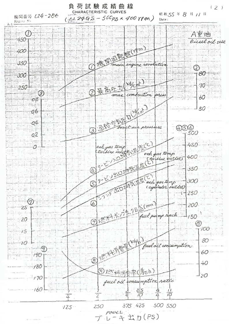
�ffl��J;x�lt±J �
(2 )
-�� ;..:.--::;::�------'-==.-=--r---r�- =
�62�2</-�$ CHARACTERISTIC CURVES
S5 8 U?l .flJ
if.
H / / rJ
( --............__ - 500p13 )( ¢00 (f;;>\\) Date:
��..:-�:�_::::... ·SQ ··'. .·.... ·--::
=: �· ·• - -soo - ·1 - .-- •--
--
-- ·· ~
"Y
,. ..
'
~) : >-·;; j>-i /_1~: _:-~ :_ ... ! . . _______ - !:::..':.:-. .:-:· :~~-- ::-· 1:-.~.~.; :~.: ;i=-. :-:.
,._
---·-·- - - -
--- - - 1 - I --,•-
- -. . \\
~:~-~ ~.;- ~> ~------~------·--- .
'.:::_i_~
+-)\\~~-- ~.-
;:·--:-- -~zs ·· - :-·--:---~
~:-. ; : _, __ ; - - .:.·- ·-- ___:.._.
I
1 ••• : •.
••
__ _ i _ ___ - - - - - - -- -
•?
'
:;--=-- •-~--1.5
·:··:.::·f.70
6,rl .. '--·----- - -- ·-/ l1
., . .
.:
- --
I
'
t:
·llS··
l
II
2.
/0
J
zso
37S: . 425 . sco -sso
( ,,
7
·0p� - ,L. ...
:_
4U.-.,.\\· JhJ
. ·" . - .
P.. S)
- -- .
--
-
.. . .. . .'
'
I
••j
.,I
·BO"-· "
-60-:,.
-40
)a·

4.8 Page 38

▲back to top
II
C
0
E
F
G
H
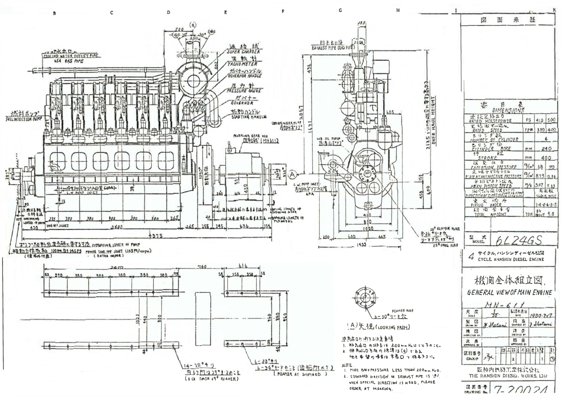
�----ifii--------
s
rtWtl lMLiff WfT \\IH!'/~)
. l 'U"TU -1\\J
IIS
.al\\ .�;t-�";D!...,.
ll1"'\\M.,li.-tln� •t. lll 9f
·:1--1.......~.i--~~u•
!:::::=i::::::ti:::=.=•
t----- - · -
IU�.--
lblll:,'-'111tl\\~
8-21,•1t ~
1~-f"K"a ..J
n+Plll\\4. N~
i
4 -ft{ �/1,, l\\:.,�:.,.,..-<--ti/1.-W,4
CYCLE. H �NSIIIN PIESEL .ENC.INE
_._ '"""�'
�.::..�0�¢
�·J�I &-4-tii.iI �.
6-EI-IERAL VIEWOfMAIN ENi/N�
��J�U.J(\\..OOl<.Jlj(j EMMJ
1 -'.l��
...!!l..1f:1Jrt,9•1-1� �.t.
l 6 a Ttt>ll' 4f� Rl4�[RJ
.!Hvli n t; !!n �ai i-'!
I. ��:-..ihn o,�l►b.•i ..too .... H.u l'A111:'(,
2. �� �O l} I'll 'l -��!.lr, (�) r H.
k!;t 4, � -, ..trl °t-frO ,. -f&�n 1 1•
.H:!TE:..
I. MAit !IA<�"-�SSU�l Ll'S.S 111,W .too.,_ H,o.
1. STlltOAU P"tn,otl 01- Ullo\\llST ptpt IS •.!-I.
..-�Lil .:lfrCl�L DIUCTI� IS H E6-D. l'l.L\\SE
O,U,Cl,. ,y HAkl(J,l4',.
�Ni fl-!��)I.l!1ti·\\ '>?ti
TIIE IIANSIDN DIESl:J. \\\\'OIIKS. l.lU
7_ ?()I) ?,d

4.9 Page 39

▲back to top
[�:Ii�it�Jw I I &I I '7TUJ ?
m
fl ,
��ii* ilmil� 5&1$rt.r-r$
I I 1J @
(P S) (rpm)
(%)
..t-m '!
:;.., IJ / 7•
ti:
:;.., IJ ::,,7·
(mm)
1T li
(mm)
A
(mm)
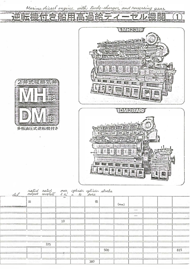
MH22R
600 430
10
6
220
390 3,970
MH23R
700 440
10
6
230 390 3,970
6MH25SSR
800 430
10
6
250 400 4,862
DM26R
1,000 405
10
6 · 260 440 4,665
DM28AR
11,1 00 1 385
10
6
280 460 5,065
DM28AR
11. 300 1 390
10
6
280 460 5,065
DM30R
11. 500 1 375
10
6
300 480 5,445
DM33R
1,600 350
19
6
330 500 5,700
DM36R
1,800 330
lb
6
360 . 540 6,347
DM38AR
12. 100 1 310
10
6
380 600 6,605
Ai.
(mm)
3,598
3,330
3,830
3,830
4,045
4,300
4,787
5,065
B
(mm)
1,050
1,050
1,100
1,200
1,220
1,220
1,330
1,370
1,400
1,500
B1
82
(mm)
(mm)
800 760
800 760
870 875
I. 910 -650
950 725
950 725
1,050 735
1,100 815
1,140 870
1,180 865

4.10 Page 40

▲back to top
.vH-
~~ ,4/,IU /U.;.:::~~iJ'=,,01=·.:1--,...,.,?41· r-=~ -- - - - - - - - - - - - - - - - - -
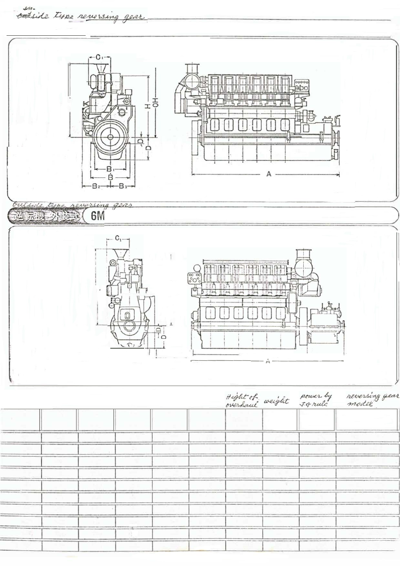
�;: MH22R•MH23R
)
I
I
c5
0
- - - - - - A - - - --
_ _y
H25SSR•DM26R•DM28AR•DM30R•DM33R•DM36R•DM38AR
I .,.--,._--ll
jo
I!
II I
i I
i I:
I l:
I
;lL.._Bl__j
-i �9..:.:___
�a-.,�•--- ------A- i --- A- -- -- -- --'----�,' .
1fa-i�6�!£.i1�:·�:��1&t,;::1:J:;}: < �: ·. _, _, .
y
81
(mm)
650
650
615
655
785
785
900
850
940
1,020
C1
(mm)
I 560
I 560
l 660
I 710
I 760
l 760
I 810
855
870
965
D
(mm)
D1
(mm)
H
(mm)
H,
(mm)
I l I I OH
(�F.9��)
(mm)
fa:
(t)
i� !fa �t
.� 1J
i2'.i: �i;
71'�
it
610 I 175 l 1,695 I 2,160 I 2,120 I 10.6 I 300 I MRL-1400 I
610 I 175 I 1,695 I 2,160 I 2,120 I 10.6 I 370 I MRL-1400 I
620 I 170 I 1,770 I 1,985 I 2,205 I 11.6 I 430 I MRL-1400A I
700 I 220 I 1,920 I 2,365 J 2,270 I 14.5 I 470 I MRL-2000A I
760 I 240 j 2,090 I 2,480 I 2,480 I 17.5 I 540 I MRL-2000A l
760 I 240 J 2,090 I 2,575 I 2,480 I 17.5 I 540 I MRL--28008 I
.800 I 250 I 2,200 I 2,607 I 2,665 I 22.8 I 630 I MRL-3000A I
900
250
2,395 2,680 2,855
26.5
760
MRL-3400A
750
20
2,600 2,795 3,090
32.0
990
MRL-4500A I
710
350
2,760 2,960 3,335
37.0 1,230
MRL-4500A

5 Pages 41-50

▲back to top

5.1 Page 41

▲back to top
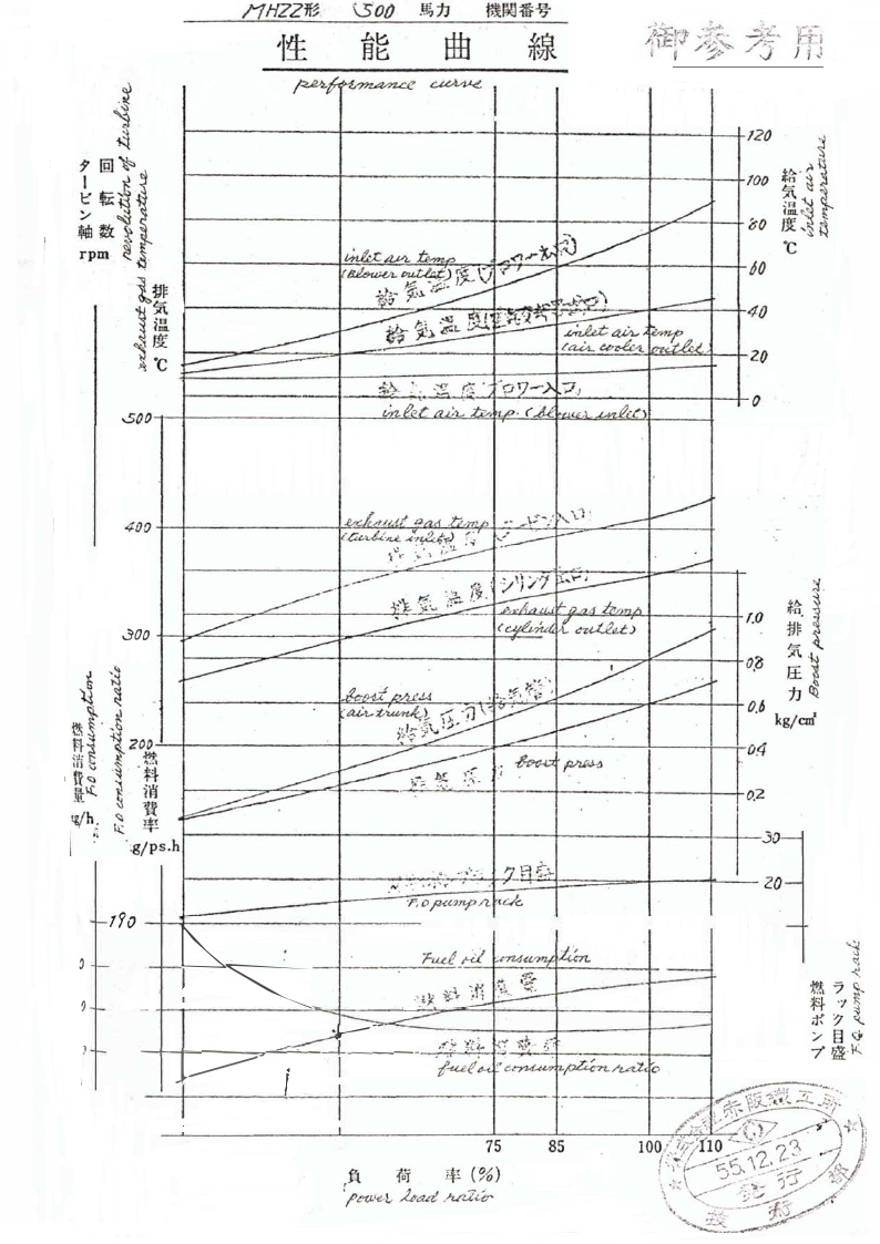
MHZZ~ \\50/) -~11 ttlOO ffi:~
'I~
.A~
§lJ
BB
*~i
~ ~ / .
'{I
I ~-ft.,. ~
I
'·l·y"'jilf'J ·.~,-~,.-...
/il t (/
/ ~ ;-
.,,
.// J:;<- -'
·1-.,
n:1
J 1J
,
C
7
~
:
~i"-
:JJ~
1r\\
---?·nen.
1Jt
~ ·c
/
~ ~ hnn--n
~~ c/
' -<1,r~
t~~)r~ I'
v - ,~ · £. J:,,,-- V
·=----- --- __..--;;;:-1;-: -~ ~/· ·- ~i;i;'-~- 1~
~~~')
.
~
~ ~ ~ ~ ,I.
------- - ~ <C/M..~ -~ ...... t7....,,
(5
00
40
20
so 0
e.~,/; ,-.,-' =t,":,. .. ..."-'~ (,i --~,;:,iJ--> ""-;;.)
I;,,,
~ ,:/p, ~.o . ( ,I I, ., ' / .Ah tJ.-/",
0
40 0
.:Joo
----- ----------------- ·<---·-~--- ----- -~
r/ o ~ l.,r/;,I-/ a.,.,.,, :;-;;,,.,, A .... \\;·-.:' ~'i..1 :
( ,tiµd.L-;r..t. #
~
~
- -~ )~Y :,:. l
·7 ~ '
~ : ";/ 1' }\\ .
:,-?.'- _r:,.. -\\~'):.. t:!-
. ~ ~
;:.•~ I - - -
/.. r, ~ .. h ~ _A
~ .( · A I ( ~ J
,kM::f bht'.J.J
V-' r.:~.
f : ~ 1 :,~ :..: I .'
~~
0
~
a# ~
~ - ; . ----- ;;.-- ·A
.
.
h
.~
~,.:d.-,:-;
·)~~\\~ ._,.,,,.,., .. ·-;] \\~
,
~
-..I.d-~-
.. ,;-.:-,... ~!. :.'·. I
~
,fVI-P,J..{J
-
- ~ lwi.
/ps.h
I. 0
o. 3
0,6
kg/cm1
()_
o. 2
30
. ... ~ .. . •.~" .
N . · ·. ~ .; '
.',.7
fl
I-
j~ -.
zo
'r, 0 ,fUC."71-f> ./2. u:.k
)O 190
---i---+-----+---!---,'0
rao - .
---1 ? 170
�-
I
,_
r u.d ~ :.=24<v=;- iJ:n,
-:tt ~ ,$
·'_t]( ~,,4..,
,l.,_, '-?,
~ .. 1
i.--
~
I .---- 160 -t--t-----=-=::_.._..__- .--A-,+-----
I
-I ; I -:-JSO
l
I
.1".~ ~i'.k- .ff ~}-- .. .
~
r,uf6-t. ,, C.c ,
~/2AZco
-
t,i' tr"''~ r:
. ,..i.:::-
G..,..,-;",";·,
\\~.,
r~"',\\\\
'""
,11,.
I
,. ~ ~~" ,. ✓• .,.~ .}
25
50
75
85
,f\\ r.r $ (%)
0f't11,1.1e,1., kad .lui2,lC'

5.2 Page 42

▲back to top
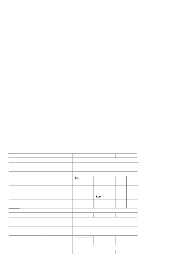
Model
Type
No. of cylinders
Bore x stroke:_··
mm
Displacement
Continuous rating output
1-hr. rating output ,.
HP
..-. HP
Engine speed
-
.. Mean piston speed·-·,:::::
B.M.E.P. <cont. rating) �--
'.;_�:,� Generator capacit)'.�'[,a:,�
rpm
mis
kg/cm2
KVA
KW
Combustion system
Compression ratio .... .,::· .. - ... -
-- Starting system
·-
Lubricating system
Cooling system .-_
Direction of rotation
Turbocharge system
Specific fuel consumption
g/HP.h.
Specific lube oil consumption (-approx.> g/HP.h.
Dry weight
kg <lbs>
6KFL
6KFL-T
6KFL-Rr.;:· ;_
4-cycle, vertical diesel engine
-. ·6
''-"
145 X 170
145
·150
1200
6.80
170
187
1500
8.50
· 16.843. ·
185 225
204 248
1200 1500
6.80 8.50
•• i.;:. ,.. . ;;_·�-
220
242 -
1200
6.80 ·__-
.. 270
297.,�:
1500 ,:.
8.50 :;-
6.46 6.06 8.24 8.01 9.80- · -9.62
·120
-� 96
.140
112
150 187.5·. 185 r .225 - 7
120
150 . 148 ·-:180 ..�:;
P re-combustion ·chamber
·--19.2
17.8
-17.8 �-"" ::"�·;
Compressed air . , . . .
-
- Forced lubrication_ with gear pump . .-.,-..
Watt!' cooling with- centrifugal pump r,:. ::-·.....:<··::·
Counter-dockwise, viewed from flywheel side
Exhaust gns turbine
Exhaust gas turbine
turbocharger
turbocharger & air cooler
200+5%
195 +5%
2.0 Cat full load>
--190 +5%
-
I I 1780 (3920)
1890 (4170)
1930 (4250)

5.3 Page 43

▲back to top
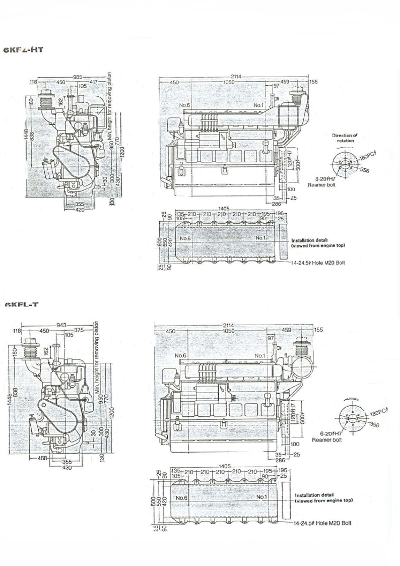
6KFL -HT
6KFL-T
CUnit=mm)
--Direction of
rotation
~l?)O?C~
s -2 0 + ~ 3 . 5 6
Reamer bolt
4-- --1-- ~ ---=-"-'-'-'-"-''"'-'----..,---+-t-t- Installation detaa
(viewed from engine top)
~ - -- - - - - - -2114!- - - - - - - - - - - --,
,., . _ _4_so,- --1--- - --1 os;n-- - ---11-- 45,4---1- -, 1ss
1
97 .~
Direction of
rotation
Installation detail
(vieweci from engine top)

5.4 Page 44

▲back to top
NFEATU ES
Bed Plate and Main Bearings cIal steel. they are heat treated and finished. Fuel Injection System
The engine block is made of cast iron. The _main
bearings consist of three layers and the inner
layer is kelmet w!th thin plated soft alloy, t11e
outer layer is made of steel. The metal caps of
the main bearing are fastened by bolts; the de­
Crankshaft
The crankshaft is made of high grade forged
steel. All pins and journals have been tempered
using ,ncuc!lon hardening and i1nished.
The fuel injection sump Is of the Bosch type, In
line model. The plunger has a sloping cut Ol
on its lower portion and it meters the volume c
fuel. The fuel valve is of the sealed type and i
automatic.
sign facilitates convenient installation or removal. Connecting Rods
The fuel pump plunger and barrel as well as th
Cylinders
The cylinders are made of high quality cast iron
and are molded with the crankcase. They are
directly in-line. A cooling water jacket is provided
between the cylinders and cylinder liners. The
liners are made of highly wear resistant special
cast iron. The inner surface is finished by honing
after being precision bored. The outer su_rface
is wrapped using anti-corrosive zinc banding.
Cylinder Head
The connecting rods are made of forged steel.
Piston p,n metals are made of lead bronze and
the crank pins of the same three !ayer material
useo In 1he main bearings. B19 end surface is
serrated to give greater rigidity.
Starting Device
The startIna device employs· compressed air
(25 or 30kg/cm2 max) system. Starting, stopping,
distribut:on and control valves are provided. Cold
weather starting remains good.
fuel valve nozzle and nozzle body are made c
specially selected special steel. These hav
been precision lapped and fitted. Additionall•
fuel filter is provided.
Governor
The governor is coup!ed to the end of the car
shaft and is mechanically operated. It is an a
speed type and it faith'ully and precisely foliov,
changes in load to automatically feedback ir
formation to the fuel pump which controls th
amount of fuel injected.
Each cylinder is independently provided with the Valves and Valve Mechanism Cooling System
cylinder head made of high quality cast iron. For
each cylinder head, fuel injection valve. intake
and exhaust valves and starting valves have
been provided; the circulation of the coolant is
good which precludes the formation of hot spots;
in particular, good cooling is provided in the
space between intake and exhaust valves.
Valves and their mechanism are all precision
manufactured. Cams, rollers and the like are heat
treated and finished by grinding. There are one
each exhaust and intake valves. These are made
of high grade heat resistant steel. The part of
valve seat is welded by heat and wear resistant
steli1te.
The cylinder cooling pump is driven by the cran
shaft at the anti-flywheel side through vee-bel
it is of the centrifugal type. The coolant passe
through to the oil cooler, respective cylinde
jackets, cylinder heads. and is discharged. 6KFl
HT; the coolant is routed to the air intercoole
before respective cylinders. A coolant regulatin
Pistons, Piston Ring Oil Rings Lubrication System
valve is provided to control the volume route
The pistons are made of high quality alumi_num; The lubncat,on pump employs the gear type, it to each cylinder.
they are of sufficient strength and durability to is mounted on the gear box housing and oper­ Supercharger:
withstand high tempera1ure and pressure on one
side. Further, they are wear resistant and all
surfaces subject to friction have been provided
with a high degree of finishing. The o:I jet is
used for cooling tile piston and its elfect,veness
is considered to be adequate. The piston rings
are highly durable and made of special cast iron.
a1es via 1he gears on the crankshaft. The lubri­
cant passes through the strainer and oil cooler
to the main bearings; hence to the connecting
rod bea-1ngs and piston pin bearings; it then
cou1s ti'e p:stons and falls to tha bottom of the
bloc� ard returns to the oil sump. A portion is
routed to tl1e cam shaft bearing, exhaust and
GKFL-T and GKFL-HT .
The supercharger ope-ates as a function of th
exhaust gas emitted frc:n the engine; it is a turbir
system of the centrifugal type. Separate lub c
pump is used for the supercharger :ubr:catin,
Cooling is accomplished by air.
There are three compression rings used and 1st intake '- alve arms, intake and exhaust valve Air Inter-cooler: GKFL-HT
ring is chrome plated One oil ring is pos,tioned tappets 'or purpose of lubricatior before it drops An inter-cooler cools a:r from supercharger an
above the piston pin and another below ,t. Piston to the bottom.
consist of multi-tube ·. th fins.
pins employ the floating system and are of spe-
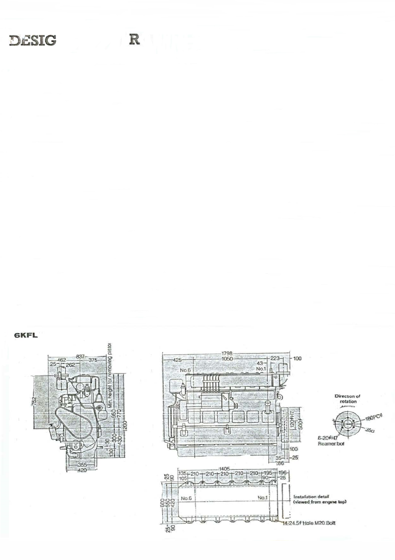
GKFL
-Oirecnon of
rotation
.
\\ SO<O ~-
6 -2DPH7
Re~
. -.::!So

5.5 Page 45

▲back to top
~
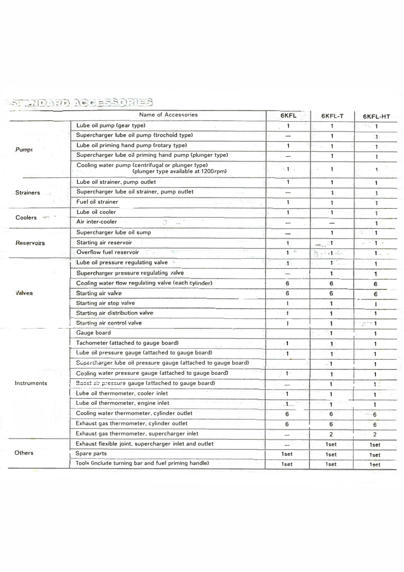
Name of Accessories
6KFL
6KFL-T
Lube oil pump (gear type)
,
Supercharger lube oil pump (trochoid type)
'1
1
-
1
Pump!
Lube oil priming hand pump Crotary type)
Supercharger lube oil priming hand pump (plunger type)
1
•· 1
-
1
Cooling water pump (centrifugal or plunger type)
··
(plunger type available at 1200rpm)
.,_1 :
-1
Strainers . -·:
Lube oil strainer, pump outlet
Supercharger lube oil strainer, pump outlet
Fuel oil strainer
.1
1
-
1
1
1
Coolers .•_...,. �
Reservoirs
Valves
-
-1--Lu-be-oil-co-ol-er-------.,.
Air inter-cooler
J
.-�.-.. ·---'---------+-----1 ---+---.-1
Supercharger lube oil sump
Starting air reservoir ·.
· Overflow fuel reservoir -:· .-
.-
·Lube oil pressure regulating valve "
-
1
1
--·.:1
-
1 .:..
'f :-•: •.1.:,.
1
1 ...__ ..
Supercharger pressure regulating 1alve
-
1
Cooling water flow regulating valve (each cylinder)
6
6
Starting air valve
6
6
Starting air stop valve
I
1
Starting air distribution valve
1
1
Starting air control valve
I
1
Gauge board
I Tachometer (attached to gauge board)
- ;·_ 1
.1
1
Lube oil pressure gauge (attached to gauge board)
1
1
Suparcl.arger lube oil pressure gauge (attached to gauge board)
_-1
Instruments
Cooling water pressure gauge (attached to gauge board)
rlub; 1 �ocst a:� ;:;�escure gauge (attached to gauge board)
oil thermometer, cooler inlet
Lube oil thermometer, engine inlet
Cooling water thermometer. cylinder outlet
" 1-
1
-
1
.1
1
..1_-
1
6
6
Others
Exhaust gas thermometer, cylinder outlet
Exhaust gas thermometer, supercharger inlet
Exhaust flexible joint, supercharger inlet and outlet
I Spare parts
Tool" (include turning bar and fuel priming handle)
6
6
-
2
-
1set
1set
lset
lset
1set
6KFL-HT
. ,-.·. 1
,1
1
'
1
1
1
1
1
-1
•' -· 1 '
1-, �-
1
1
6
-6
I
·1
1 . ;�...'r'
1
1
1
1
1
I
I
, 1 �-
·1 -
1
--6
6
-2
1set
1set
1set